
G&L Passive Treble Bass (PTB) Circuit for HSS Stratocaster
| 08/06/2025 | Written By: Kim Ippolito | Formatted/Edited By: Lauren Ippolito |
While researching what other mods I could apply to my HSS Stratocaster, I came across the G&L Passive Treble Bass (PTB) Circuit. I wanted to combine both the PTB circuit and the Volume Treble-Bleed Circuit (TBC). My first attempt was to use the design as-is, but the results weren't as impressive as I was expecting. In this blog, I walk through the analysis that I used to select the circuit parameters (resistor values, capacitor values, etc.) for my configuration.
(If you want to skip the analysis, and go straight to the circuit parameters, then go to the Summary section near end of this blog.)
So what is the G&L PTB Circuit?
The G&L Passive Treble & Bass Circuit has three stage: a Treble Cut stage (like the standard Tone control), a Bass Cut stage, and a Volume stage. Here is G&L's diagram that is floating around the internet:

In a typical two-stage Tone & Volume circuit, the tone circuit only performs the Treble-Cut, which shapes the treble response and keeps the bass intact. The addition of the Bass-Cut stage between the Treble-Cut and Volume stages adds the ability to shape the bass response as well. Pretty cool...
Are there any drawbacks? Well, yes - the way it is designed, it assumes a global tone control. It also requires two tone knobs. For my HSS stratocaster build, this isn't a problem since I wanted a global tone control, and I have three knobs on my pickguard - one for the Volume, one for the Tone Treble-Cut, and one for the Tone Bass-Cut.
An alternative is to have separate tone controls for the Treble-Cut, but have global Tone Bass-Cut control (which would require an additional pot knob on your pickguard). Another alternative is to have two Tone Treble-Cut controls, and have a push button that turns on the Bass-Cut at a particular fixed level (which takes up less space than a potentiometer knob).
For my setup, I am going with a global Tone control, with two knobs for Tone: a Treble-Cut knob and a Bass-Cut knob.
How to Determine Best Settings?
One way is to just try it out, and then adjust options based upon what you hear.
Well, I did that, but each time I wanted to change something (such as a capacitor value), I had to take off the strings, pull of the pickguard, unsolder the component, and solder in a new component. To compare the results, I recorded the sound of the modification on my computer (I used my Behringer UPhoria UMC1820 to do this, but you can simply use a microphone.)
This approach wasn't all that effective. It did give me an understanding of how the PTB circuit affects my tone, but it didn't give me a way to easily optimize the parameters. So I changed tactics and decided to simulate the guitar's response via LTSpice. This allowed me to simulate the different changes without having to modify the guitar. This didn't give me any audio feedback about the change, but it did help me visualize the impact of any given change.
There are a few good references on how to do this, particularly this one:
https://guitarnuts2.proboards.com/thread/7842/modeling-electric-guitar-ltspiceHere is what my circuit looked like in LTSpice:
If you are interested, I include more information about how I set up this LTSpice diagram in the last section of this blog.
But does simulations help select the best parameters for the circuit? No, not on its own. The simulations only show the frequency response over the full range. So it doesn't tell you how it actually sounds in your guitar, how it sound when you only play an open chord, how it sounds when you are soloing on the frets near the neck, etc. So it does give you good intuition on how the tone is changed, but not how it actually sounds. So you need to combine this information, along with knowing how you play the guitar, what you play, how your guitar sounds without the PTB circuit, and what tone adjustments you think would be beneficial to you and your guitar.
Baseline Results
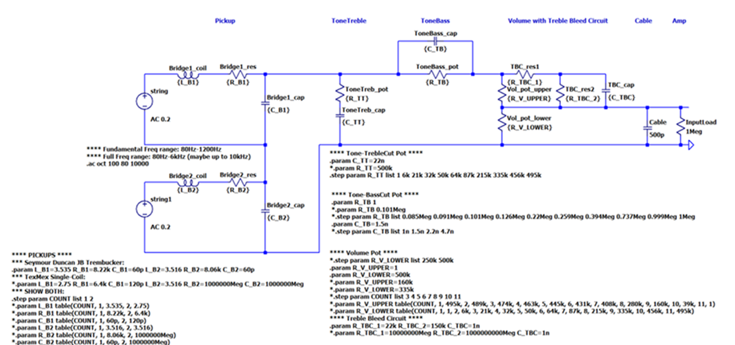
So the first thing to do was determine the baseline frequency response of my guitar, containing just my pickup, cable wire, and amplifier.
To do this I had to determine the R, L, and C values of my different pickups. The pickups that I have are:
- Bridge: Seymour Duncan JB Trembucker (Humbucker)
- L = 3.535 Henry, R = 8.22k Ohms, C = 60pF
- L = 3.516 Henry, R = 8.06k Ohms, C = 60pF
- Middle & Neck: Fender Tex-Mex Single-Coil
- L = 2.75 Henry, R = 6.4k Ohms, C=120pF
Thus, I am able to create frequency responses for both the Seymour Duncan Humbucker (in series) and a Fender Tex-Mex single-coil, modeling the cable as having C=500pF, and the input load of the amplifier being 1Meg Ohm.
Here is the baseline frequency response of the circuit for both Humbucker (Green) and Single-Coil (Blue):
From the diagram, you can see that the resonant peak of the single-coil is shifted to right of humbucker, making it brighter than the humbucker.
So now let's start looking at how the volume and tone stages affect this baseline result, and select the optimal parameters for the volume and tone circuits.
Selecting Volume Pot's Resistance Value
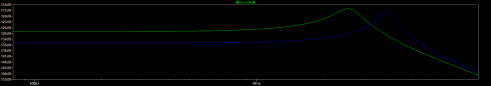
The volume potentiometer’s resistance value helps tame the resonance frequency peak. Here is what happens if we use a 250k volume pot:
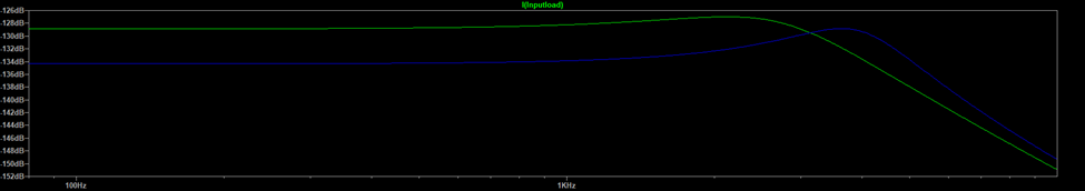
The 250k works pretty well for single-coil, but overly smooths the high frequencies for the humbucker. Here is what happens if we use a 500k volume pot instead:
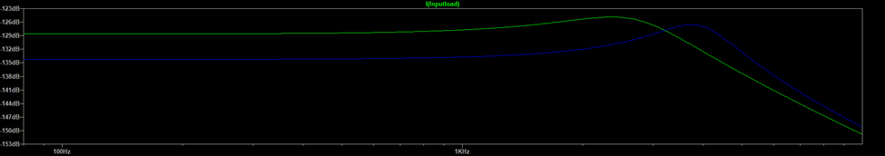
The 500k is a good compromise between the single-coil and humbucker. Any additional taming of the single-coil can be accomplished by the tone controls.
Thus, for my volume circuit, I will use a 500k Ohm audio-taper potentiometer.
This choice differs from the G&L circuit diagram shown earlier which has a 250k potentiometer (since the diagram was probably for an SSS guitar not an HSS).
Adding a Treble Bleed Circuit (TBC) to Volume Pot
In my circuit, I want to add the TBC circuit to the PTB circuit to prevent the volume level from interfering with the PTB tone knobs. This section shows the impact of the volume level on the tone without TBC, the parameters that I selected for the TBC, and how the TBC circuit improves the result.
The previous plots were generated with the volume at 100%. Changing the volume level impacts the tone, suppressing the high frequencies, as shown in the following two diagrams, which shows what happens when you change the volume knob (an audio taper potentiometer) from 3 to 10 without the Treble Bleed Circuit. Here are the results with the single-coil:
and with the Humbucker:
The impact of the volume level on the high frequencies is not a desired side-affect! This is where the Treble Bleed Circuit (TBC) comes in.
The Treble Bleed Circuit is designed to fix this problem - it will minimize the affect of the volume level on the high frequencies. With the TBC circuit, the shape of the high frequencies response curve is preserved as the volume is rolled off. I added the TBC to the PTB circuit, using the following Fender's TBC design:
https://www.fender.com/articles/maintenance/how-a-treble-bleed-circuit-can-affect-your-toneThis version adds 2 resistors and one capacitor to the volume potentiometer. The addition of TBC makes the Single-Coil's frequency response more consistent across volume levels:
and the same is true for Humbucker:
There are at least two other configurations that you could consider - without resistors, without resistor 1, and without resistor 2. The results do slightly change the plots above (mainly around the resonant peak), but I wasn't able to provide an intuitive explanation of how much those differences actually affect the sound produced as heard by the ear, so I didn't include those plots in this blog (to prevent from muddying the waters). But needless to say, any of those alternatives will reduce the affect that the volume level has on the tone. I also stuck with the parameters defined by Fender.
Thus, for my volume circuit, I added Fender's version of TBC using the following parameters: 22kOhm, 150kOhm, and 1nF.
Selecting Tone Treble-Cut Capacitor
The next thing to determine is the Tone Treble Cut capacitor, which is typically either 0.022uF or 0.047uF.
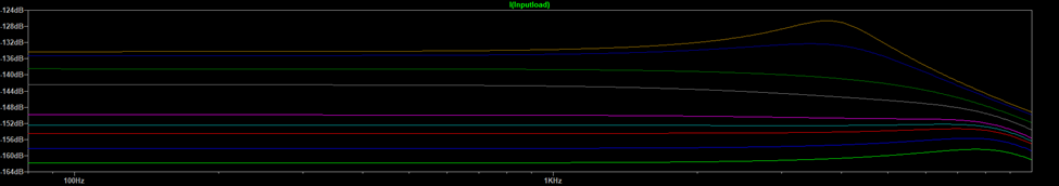
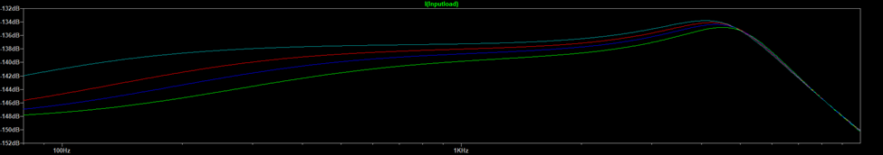
Here are the results of the 0.022uF capacitor on the Single-Coil (for different knob values between 10 and 1):
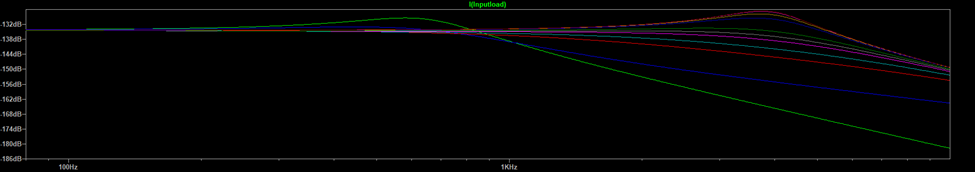
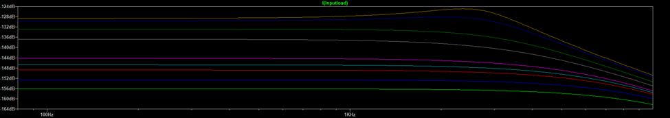
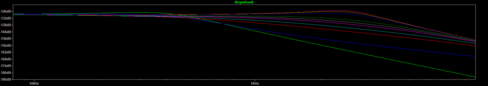
and the results of the 0.022uF capacitor on the Humbucker:
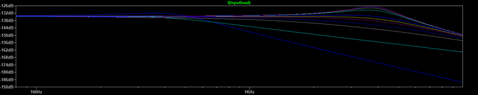
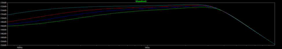
Here are the results of the 0.047uF capacitor on the Single-Coil:
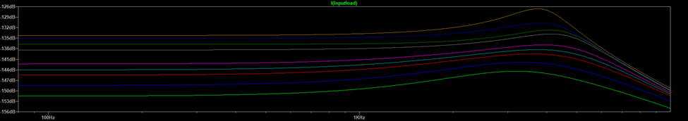
and the results of the 0.047uF capacitor on the Humbucker:
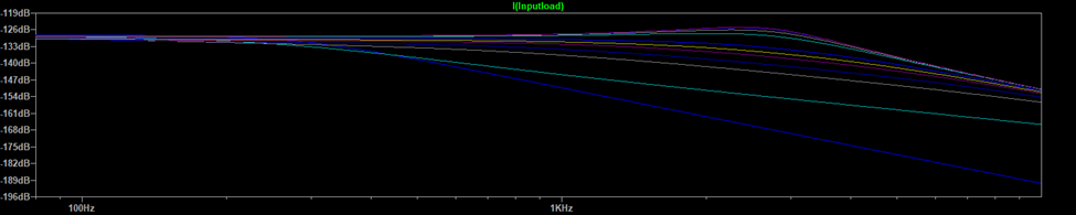
The 0.047 uF rolls off the lower frequencies slighter more than the 0.022 uF capacitor, particularly for the humbucker. But both are good options.
In my setup, I am going to go with the 0.022 uF for the Tone Treble-Cut capacitor.
Selecting the Tone Bass-Cut Capacitor
The next thing to determine is the Tone Bass-Cut capacitor – 1nF, 1.5nF, 2.2F, or 4.7nF.
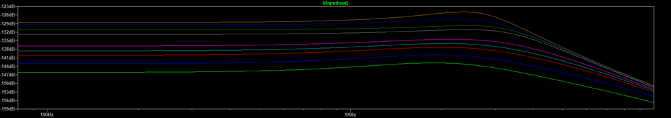
With Volume at 80% and Tone Treble Cut at 80%, and 1MOhm Bass Cut Resistor (at 0%), the four different Tone Base Cut capacitors were evaluated, as shown below for the Single-Coil:
and for the Humbucker:
The 1nF (the lowest line) provides a nice reduction of the lower frequencies, but it also reduces the resonant peak. The 1.5nF doesn’t reduce the resonant peak as much, so it appears to be a good compromise.
Thus, for my setup, I will be using 1.5 nF for the Tone Bass-Cut capacitor.
Selecting the Tone Base-Cut Potentiometer Resistor Value
The original design called for a 1MOhm potentiometer with inverse log taper. However, some people have claimed to find success with 500kOhm potentiometer with linear taper.
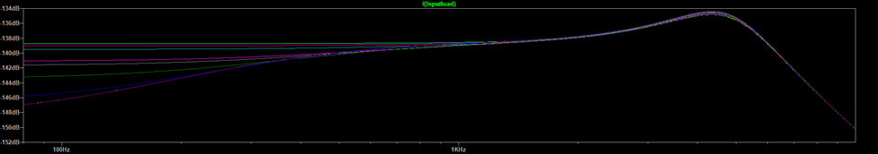
The following diagrams show the result of sweeping across the different knob positions (1 to 10) of a 1MOhm potentiometer with inverse log taper. Here is the Single-Coil:
and the Humbucker:
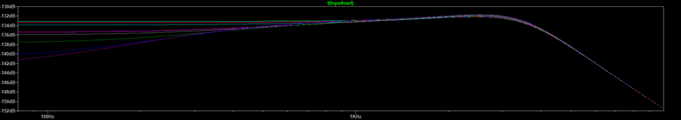
The diagrams show that the 1MOhm gives a decent range of low-frequency attenuation levels. If it were 500MOhm, the range would be significantly reduced.
So, for my setup, I will be using a 1MOhm inverse log taper potentiometer for the Tone Bass-Cut circuit.
Summary
So here is what my complete Volume and Tone stage looks like (including a Blower Switch):
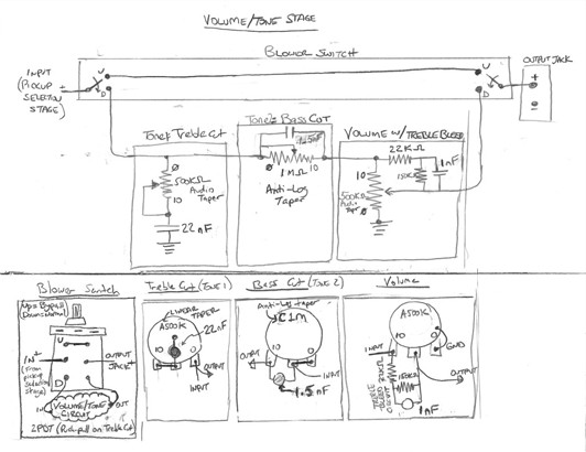
Where:
- Tone Treble-Cut:
- 500 kOhm Audio Taper Potentiometer
- 22 nF Capacitor
- Tone Bass-Cut:
- 1 MOhm Anti-Log Taper Potentiometer
- 1.5 nF Capacitor
- Volume:
- 500 kOhm Audio Taper Potentiometer
- 22 kOhm and 150 kOhm resistors
- 1 nF Capacitor
- List
Appendix: LTSpice Simulation
This section details how I used LTSpice to produce the plots in this blog...
As shown in the LTSpice diagram earlier, I set up the circuit assigning variable names to all components that I wanted to potentially vary.
Then, I set up a Spice Directive section for each stage (Pickups, Tone-Treble-Cut, Tone-Bass-Cut, Volume with TBC). In each of these, I define several variations of the values, with all but one configuration commented out (with a "*" in front). For example, I may define the values as if the pot knob is at one or more fixed values (such as 10 and 8), and also a sweep of values (such as changing the pot knob from 1 to 10, or a range of capacitor values). At any time, I can only have one of the configurations available, with all of the others "commented-out". And if I want to change the configuration, I only need to change which lines are commented-out.
More specifically, here are the configurations I have in each section.
The Pickups Stage:
**** PICKUPS ****
*** Seymour Duncan JB Trembucker:
.param L_B1=3.535 R_B1=8.22k C_B1=60p L_B2=3.516 R_B2=8.06k C_B2=60p
*** TexMex Single-Coil:
*.param L_B1=2.75 R_B1=6.4k C_B1=120p L_B2=3.516 R_B2=1000000Meg C_B2=1000000Meg
*** SHOW BOTH:
.step param COUNT list 1 2
*.param L_B1 table(COUNT, 1, 3.535, 2, 2.75)
*.param R_B1 table(COUNT, 1, 8.22k, 2, 6.4k)
*.param C_B1 table(COUNT, 1, 60p, 2, 120p)
*.param L_B2 table(COUNT, 1, 3.516, 2, 3.516)
*.param R_B2 table(COUNT, 1, 8.06k, 2, 1000000Meg)
*.param C_B2 table(COUNT, 1, 60p, 2, 1000000Meg)
The above code is configured for the Humbucker (the Seymour Duncan JB Trembucker), which sets the parameters for both pickups in series.
If I want to test the Single-Coil instead, I comment out the Seymour Duncan parameters and un-comment the TexMex Single-Coil parameters. The parameters for the Single-Coil define the first pickup as a TexMex pickup, and short-circuits the second pickup.
Alternatively, if I want to show the comparison between the two, I make sure the parameters for the Seymour Duncan Trembucker and the Tex-Mex Single-Coil are commented out, and uncomment all of the parameters in the "Show Both" section.
The same organization applies to the other stages, as shown below.
The Tone-Treble-Cut stage:
**** Tone-TrebleCut Pot ****
.param C_TT=22n
*.param R_TT=500k
.step param R_TT list 1 6k 21k 32k 50k 64k 87k 215k 335k 456k 495k
The Tone-Bass-Cut stage:
**** Tone-BassCut Pot ****
.param R_TB 1
*.param R_TB 0.101Meg
*.step param R_TB list 0.085Meg 0.091Meg 0.101Meg 0.126Meg 0.22Meg 0.259Meg 0.394Meg 0.737Meg 0.999Meg 1Meg
.param C_TB=1.5n
*.step param C_TB list 1n 1.5n 2.2n 4.7n
The Volume with TBC stage:
**** Volume Pot ****
*.step param R_V_LOWER list 250k 500k
.param R_V_UPPER=1
.param R_V_LOWER=500k
*.param R_V_UPPER=160k
*.param R_V_LOWER=335k
*.step param COUNT list 3 4 5 6 7 8 9 10 11
*.param R_V_UPPER table(COUNT, 1, 495k, 2, 489k, 3, 474k, 4, 463k, 5, 445k, 6, 431k, 7, 408k, 8, 280k, 9, 160k, 10, 39k, 11, 1)
*.param R_V_LOWER table(COUNT, 1, 1, 2, 6k, 3, 21k, 4, 32k, 5, 50k, 6, 64k, 7, 87k, 8, 215k, 9, 335k, 10, 456k, 11, 495k)
**** Treble Bleed Circuit ****
.param R_TBC_1=22k R_TBC_2=150k C_TBC=1n
*.param R_TBC_1=10000000Meg R_TBC_2=1000000000Meg C_TBC=1n
Bypass (Blower Switch):
The "bypass" case (equivalent to a "blower switch") only includes the pickups, cable, and amp. To simulate this in LTSpice, I had to modify the Spice diagram to produce that particular plot.